[기술] KNX : 현대식 건물에 적합한 제어 시스템
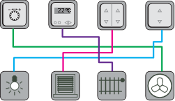
The demand for comfort and versatility in either residence or commercial building is growing fast in recent years. It implies a complex system covering intelligent control, low energy consumption, high-level security should be involved. In the past, the system is quite complicated in terms of electrical wiring because each function of the device needs its own physical control cable shown in Figure 1. It requires a large amount of effort in terms of design and installation at the beginning and later deploys the high difficulty on maintenance.
The high density of cables could also have a high risk of fire. Therefore, a new installation for uni-communication between any controller, sensor, and actuator are developed and named with the KNX system. The KNX system uses only two-wire installation bus routed transmitting the signals between devices in parallel to the 230 VAC mains wire. Therefore, the KNX system substantially reduces the mass work of electrical wirings inside the building and further lower fire risk and maintenance.
 vs.
vs. 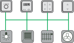
Figure 1 Traditional system (left) vs. KNX system (right)
Power Supply for KNX Bus
The KNX system can not only be very simple with few devices but also be extended a complex system with hundreds of device for use in a building. In both cases, KNX power supply is needed for powering the KNX Bus. In this part, it explains why a KNX power supply is essential for KNX Bus environment and it cannot be replaced with conventional switching mode power supply. The first scenario is just a simple system with only two devices (wall flush button and an actuator for controlling electrical blind) on the KNX Bus shown in Figure 2. In case the user press the button in order to turn on the electrical blind and see through the window, it turns out this system is not functioning. The digital command from a button cannot be transmitted to the actuator for controlling the blind simply because the KNX Bus is not powered. However, the second scenario is 30 Vdc conventional power supply added into the existing Bus. Now the button could transmit the signal out, the so-called active pulse, on the bus. However, the actuator is still not able to receive and further response to it because this signal is not a complete and proper KNX signal. In the third scenario, a KNX Power supply with integrated choke is added into the system. When the button transmits the active pulse signal onto the Bus, the KNX Power supply will response an equalization pulse immediately due to the integrated choke.The active and equalization pulse is then combined to realize a correct signal representing “0” in the digital world. The combined waveform should be finished within 104 µsec which is equivalent 10 kHz following with another combined waveform for “0” or no waveform( just 30 Vdc) for “1” in the next 104 µsec. Such “0” & ”1” sequential numbering represents the actual function/command from the button to the targeted actuator of the blind system. As result, this simple KNX system is operating properly. Other KNX devices, e.g. lighting, heating, HAVC, security...etc., have the same working principle on the same and only one bus for maximum flexibility. Each KNX device consumes 10 mA from the power supply for transmitting and receiving a signal on the bus. In case the KNX power supply is rated 640 mA, it implies the maximum allowable number of the device on the bus is 64 pcs. Hence, the KNX Power supply with integrated choke is very essential to keep the normal operation of the KNX Bus system.
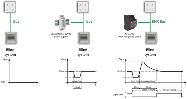
Figure 2 Scenario 1 the bus is not powered (left); The bus is powered but not by KNX Power supply (middle); The complete and working KNX Bus system that sending the correct digital “0” & ”1” command for communication (right)
KNX Actuator
A KNX actuator converts the commands received from sensors, automatic control switches or timers into actions and form the interface between the KNX system and the electrical devices typically implementing for lighting, blinds and heating applications.Currently, the mainstream and economical solution is actuator implemented with mechanical relay(s) to turn ON or OFF on any type of loads connected to it as shown in Figure 3.
Figure 3 A compact (4 standard unit) KNX actuator equipped with 8 pcs mechanical relay
A good quality relay is the key role to ensure high reliability for switching actuators used in a KNX building automation system.
EN60669-1: Switches for household and similar fixed electrical installations – General requirements is one of the standards to define the performance and endurance of relay.
Part 19.1 of EN60669-1 specifies the normal operation of the relay which is intended to connect a rated load with costƟ =0.6 and the target is to meet at least 40000 number of operations. The typical current rating is 16A or 10A depending on the application demand.
The designation AX has established a (capacitive) fluorescent lighting load. A test with 140 µF is the minimal requirement and should operate at least with 10000 number of operations. Actuator products from MEAN WELL are further tested to 220 µF on top of the basis of EN60669-1
part 19.2. Since the LED driver is not yet regulated in the EN60669-1. It is considered as a capacitive type of load due to the major circuitry design of common LED driver. As result, part 19.2 can be applied to LED driver type of load for the relay in a KNX actuator.
Another standard EN 60947-4-1: Contactors and motor-starters – Electromechanical contactors and motor-starters are also referred in KNX actuator. The tests are defined to simulate typical applications, e.g. motor loads (industrial) or fluorescent lamps (residential). Specifications AC1 and AC3 are switching performance specifications which have become established in the industrial field.
The following designations in EN60947-4-1 are commonly used in KNX building automation:
AC1 – Non-inductive or slightly inductive loads, resistance furnaces (relates to switching of resistive loads, cos Ɵ = 0.8)
AC3 – Squirrel-cage motors: starting or switching off during running (relates to (inductive) motor load, cos Ɵ = 0.45)
AC5a – Switching of electric discharge lamps
AC5b – Switching of incandescent lamps
The above conditions should pass with at least 6000 number of operations.
Size matter
All KNX devices including power supply, input device, and actuator are in general installed in a distribution board cabinet within a building. A typical cabinet example is shown in Figure 4.The dimension of the KNX device should be designed according to the standard DIN 43880 to make sure installation uniformity. The width of the KNX device is coded by one or multiple standard units (SU) by definition each very single SU should not be more than 18 mm.
Current mainstream 640 mA KNX Power supply has 4 SU(54mm) width or more whereas 1280 mA KNX Power supply has 6 SU(108mm) width or more. MEAN WELL KNX products with slim design i.e. 3 SU for 640mA and 4SU for 1280mA power supply allows more other KNX device to be installed in the fixed space within the cabinet which enables versatile functions for modern buildings.
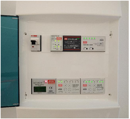
Figure 4 A common 2 rows 12 SU distribution board cabinet with the installation of the circuit breaker and KNX devices
Conclusion
KNX system offers a lot of benefits for operating in modern residential and commercial buildings. KNX power supply is a key unit and device to run the KNX system smoothly. MEAN WELL offers 640mA KNX Bus power supply with 3 SU size and 1280mA version with just 4 SU size.Another KNX unit to enable the electrical devices is an actuator made with mechanical relays. A well designed KNX actuator should subject to the corresponding standard depending on applications to ensure a long and stable operation with minimized maintenance and service.
MEAN WELL KAA series multi-channel actuator offers 16A or 10A with 4SU compact size and all units are tested by notified laboratory with test reports provided. With over 35 years of industrial power supply experience,
MEAN WELL KNX products are engineered to be a reliable and safe solution for the KNX system.
제품문의 사항은 에버넷전자 영업부 (+82-31-465-2206)로 연락 바랍니다.
원글 출처 : MEANWELL / 국문 번역: 에버넷전자