[기술] 고압 고용량 출력제품과 적용 제품
요약 내용:
UV 경화 장비 및 레이저 장치 분야에서 고전압 출력 제품에 대한 요구가 점차 증가하고 있습니다.
적합한 고전압 출력 전원 공급 장치가 없을 때 직렬로 연결하였는데, 이는 콜드 스타트 동안 손상을 방지하기 위해 추가 다이오드가 필요하며, 비용이 상승하고, 고장률과 복잡성이 증가하였습니다. CSP-3000 시리즈는 이러한 문제를 극복하기 위한 완벽한 모델입니다.
출력 전압 및 출력 전류는 PV / PC 기능을 통해 조정할 수 있습니다.
In the past, power supplies complied with SELV with low voltage output are commonly used, such as 3.3V/5V/12V output for ATX power supply, 19V~24V adapters for lab top and 12V/24V/48V for industrial power supply. However, nowadays, the demand for high voltage output applications are growing gradually, in the fields such as UV curing equipment and laser apparatus.
Numbers of power supplies were connected to achieve high voltage output (Figure 1.)when there was no suitable high voltage output power supply. Extra diodes are required to prevent damage during cold start. Not only does the cost go up, but also failure rate and complexity are increased. Undoubtedly, CSP-3000 series is the perfect models for overcoming these issues.
.png) |
| Figure 1. Power supplies connected to achieve high voltage output |
CSP-3000 is a 3kW AC/DC single output power supply with input range from 180~264Vac, providing high voltage DC output needed the most in the market. CSP-3000 is capable to operate under ambient temperature up to 70℃(Please refer to derating curve) with forced fan cooling topology. Moreover, CSP-3000 is build-in with multiple features, such as PV/PC, parallel, remote on/off and aux winding, which highly increases the flexibility of usage.
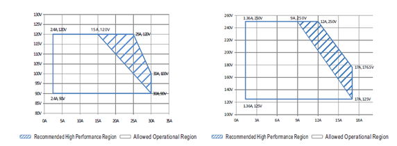
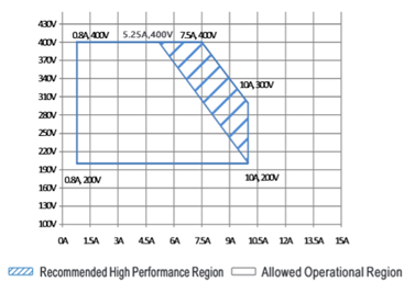
To apply CSP-3000 series in LED application, operating under the blue operating region from figure 2 ~ figure 4 is recommended, where to ensure the best performance of CSP-3000.
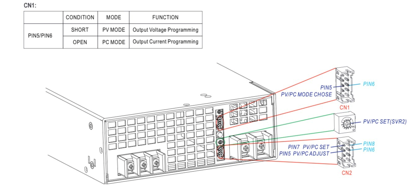
Output voltage and output current can be adjusted through PV/PC function. Either PV or PC function can be activated through PIN5/PIN6 on CN1. If Pin5/Pin6 is shorted, PV function is activated, vice versa, PC function is activated.
 |
||
| Figure 2. CSP-3000-120 | Figure 3. CSP-3000-250 | |
 |
||
| Figure 4. CSP-3000-400 | ||
 |
||
| Figure 5. PV/PC Mode and Pin Function Mechanism | ||
 |
||
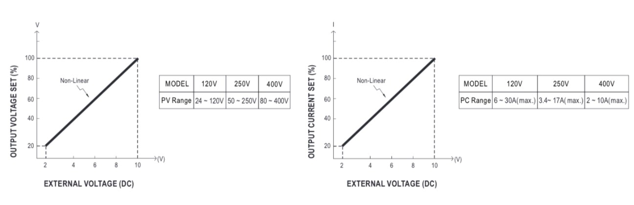
| Figure 6. Vo-Vs Chart | Figure 7. Io-Vs Chart | |
 |
||
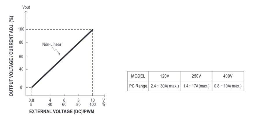
| Figure 8. Vo/Io-Vs Chart | ||
There are three ways to adjust output voltage under PV function mode. 1st method is using SVR2 to adjust output voltage within the adjustment range from 20% ~ 100%. 2nd is by applying a DC voltage signal Vs between PIN7/PIN8 within the adjustment range from 20% ~ 100%(shown as figure 6) when Vs < 2V, Vo ≧ 10% of the rate voltage. 3rd is by applying a DC signal Vs between PIN5/PIN6, with wider adjustment range from 8% ~ 100%, and also perform better during dynamic situation. Please refer to figure 8 for reference.
Under PC mode, SVR2 is used to set the maximum constant current protection point Imax. There are 2 ways to adjust the output current Io, 1st one is to adjust through CN2 by applying a DC voltage signal Vs on PIN7/PIN8, and posses adjustment range from 20% ~100% (shown as figure 7). 2nd is by apply a DC signal Vs between PIN5/PIN6, with wider adjustment range from 8% ~ 100%, and perform better during dynamic situation also. Please refer to figure 8 for reference.
For a better understanding, please refer to the following video.
제품문의 사항은 에버넷전자 영업부 (+82-31-465-2206)로 연락 바랍니다.
원글 출처 : MEANWELL / 국문 번역: 에버넷전자